Introduction to Hydraulic Pressure Safety Systems
Hydraulic pressure safety systems are the engineered controls, devices, and procedures that protect people, equipment, and facilities from the hazards created by pressurised hydraulic fluid. In 2026, industrial environments—spanning construction, manufacturing, agriculture, and marine operations—these systems are not optional extras but fundamental requirements for safe operation. Every hydraulic circuit stores significant energy in the form of pressurised fluid, and without proper safety measures, that energy can be released in ways that cause serious injury, equipment destruction, and costly downtime.
Modern hydraulic systems routinely operate between 140–350 bar (2,000–5,000 psi), with some specialist applications exceeding 700 bar (10,000 psi). Under these pressures, even small volumes of hydraulic fluid contain enough stored energy to cause catastrophic failures if released uncontrollably. A pinhole leak at 200 bar can penetrate skin and inject fluid deep into tissue. A failed hose can whip with enough force to cause severe injuries or fatalities. This stored energy is the core safety concern that underpins every aspect of hydraulic system design, operation, and maintenance.
The approach to managing these risks combines three elements: correctly specified hydraulic pressure safety devices, disciplined maintenance work, and strict adherence to hydraulic system safety standards. Together, these pillars form a comprehensive defence against overpressure, leaks, contamination, and accidental movement. Overpressure protection in hydraulic systems will be covered in depth throughout this guide, as it represents one of the most critical—and most commonly misunderstood—aspects of hydraulic safety. As specialists in designing, maintaining, and troubleshooting safe hydraulic installations, we’ve seen firsthand how proper safety systems prevent accidents and protect both people and equipment.
Key risks addressed by hydraulic pressure safety systems:
- Overpressure leading to component rupture and fluid release
- Overheating causes fluid degradation and seal failure
- Contamination compromises component function and reliability
- Human error during operation, maintenance, or repair work

Key Hydraulic Pressure Hazards Operators Must Understand
Operating pressures above 140 bar (2,000 psi) create workplace hazards that can materialise in seconds. The most common pressure-related accidents include hose bursts that release high-velocity fluid jets, fluid injection injuries from pinhole leaks, unexpected load movement when valves fail or are bypassed, and fires when hydraulic oil contacts ignition sources. Understanding these hazards is essential for anyone who works with or around hydraulic equipment.
The relationship between pressure, flow, and force is governed by a simple formula: Force = Pressure × Area (F = P × A). This means that even a “small” hydraulic cylinder with a bore of just 50mm, operating at standard industrial pressures of 200 bar, can generate over 39 kilonewtons of force—roughly equivalent to lifting a 4-tonne vehicle. When loads are suspended by hydraulic actuators, this force becomes stored energy that must be safely controlled and released.
Real-World Pressure Incidents
Consider these realistic scenarios that illustrate why pressure hazards demand respect:
- A 210 bar (3,000 psi) hose burst in a workshop sprays fluid across a 5-metre radius in under two seconds. Anyone in that zone risks burns, eye injuries, and slip hazards from oil spills.
- A technician checks for leaks by running a bare hand along a hose operating at 100 bar. A pinhole leak, invisible to the eye, injects fluid through the skin and into underlying tissue—an injury that can lead to amputation if not treated surgically within hours.
- A relief valve on a mobile crane is incorrectly adjusted 15% above the cylinder’s rated pressure. During a heavy lift, the cylinder rod seal fails catastrophically, dropping the load without warning.
- An accumulator is not depressurised before maintenance. When a fitting is loosened, the stored gas pressure forces hydraulic fluid out at high velocity, striking the technician.
- A section of isolated pipework retains full system pressure after shutdown. A fitter who assumes the line is depressurised removes a union and is struck by the fitting as trapped pressure releases.
These scenarios highlight how quickly pressure hazards can escalate. The critical point is that stored energy remains dangerous even when pumps are stopped, and machines appear idle.
Summary of Main Pressure-Related Hazards
- Stored energy in accumulators, suspended loads, and isolated pipework
- High temperature causes fluid thinning, seal degradation, and burn risks
- Ignition potential when atomised hydraulic oil contacts hot surfaces or sparks
- Injection injuries from high-pressure leaks penetrating the skin
- Component rupture due to overpressure or fatigue failure
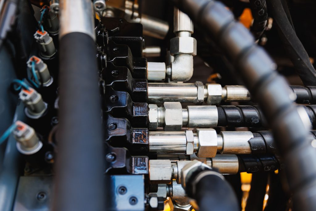
Core Hydraulic Pressure Safety Devices and How They Work
This section provides a practical overview of the main hydraulic pressure safety devices used to keep systems within safe limits and to deliver effective overpressure protection in hydraulic systems. Each device has a specific function, a typical setting range, and a location within the hydraulic circuit. Understanding these devices is essential for operators, technicians, and engineers responsible for safe operation.
Pressure Relief Valves
Pressure relief valves are the primary mechanism for protecting hydraulic components from excessive pressure. They function by opening at a pre-set pressure, allowing fluid to bypass back to the reservoir when system pressure exceeds the safe threshold. For mobile plant, typical relief valve settings range from 180–250 bar, matched to the pressure ratings of pumps, hoses, and actuators in the circuit.
Relief valves must be matched to the lowest-rated component in the circuit they protect. If a relief valve is set too high, components can fail before the valve opens. If set too low, the system cannot develop the pressure needed for the intended work. Getting this balance right is fundamental to both safety and performance.
Pressure Safety Valves
Pressure safety valves function as last-resort protection devices. Unlike standard relief valves that may modulate flow, pressure safety valves provide a rapid “pop” action that fully opens when pressure exceeds the maximum allowable working pressure. These devices protect against catastrophic rupture or explosion in applications where the consequences of overpressure are particularly severe, such as large accumulators or high-energy test rigs.
Pressure Reducing Valves
A pressure-reducing valve maintains a lower, stable downstream pressure while the main system operates at a higher pressure. This is essential for protecting delicate components such as pilot lines, clamping circuits, or control valves that cannot withstand full system pressure. By isolating sensitive functions from the main high-pressure circuit, pressure-reducing valves enable complex systems to operate safely with multiple pressure zones.
Counterbalance and Pilot-Operated Check Valves
These valves control overrunning loads and prevent unintended movement of cylinders and actuators. In applications such as lifting platforms, cranes, and access equipment, counterbalance valves hold loads securely even if hoses fail or the pump stops. Pilot-operated check valves lock cylinders in position until a deliberate control signal releases them, providing vital protection against gravity-driven movement.
Accumulators
Accumulators serve as pressure storage reservoirs, holding hydraulic fluid under pressure using a pre-charged gas (typically nitrogen). While they provide useful functions such as energy storage and shock absorption, they also represent a significant safety consideration. Correct pre-charge pressure is critical, and accumulators must be safely isolated and depressurised before any maintenance work. Failure to do so can result in the violent release of stored energy.
Pressure Relief Valves and Overpressure Protection
Pressure relief valves underpin overpressure protection in hydraulic systems. Without a functioning relief valve, or with one that is blocked or incorrectly adjusted, pressure can build until the weakest component fails. This might be a hose, a seal, or the valve plate of a pump—any of which can fail catastrophically under excessive pressure.
Key points for relief valve setting and testing:
- Set the relief pressure just below the maximum working pressure of the lowest-rated component in the protected circuit. For a system operating at 2500 PSI (172 bar), industry guidance suggests setting the relief valve between 2650–2800 PSI (183–193 bar) to provide adequate protection while allowing normal operation.
- Factor in pump capability and duty cycle. Continuous high-pressure operation may require more conservative settings than intermittent use.
- Consider an excavator auxiliary circuit rated at 250 bar feeding a tooling attachment rated at only 210 bar. If the relief valve is not adjusted down to protect the attachment, the lower-rated component can fail under normal system pressure.
- Modern high-flow or high-pressure circuits often use pilot-operated relief valves for stable pressure control, while direct-acting valves suit compact, lower-flow applications.
- Regular functional testing of relief valves is a requirement under many hydraulic system safety standards and should be part of scheduled maintenance routines. Testing verifies that the valve opens at the correct pressure and flows adequately to protect the system.
Additional Hydraulic Pressure Safety Devices and Instrumentation
Beyond the primary pressure control valves, a range of instruments and secondary devices contribute to pressure safety.
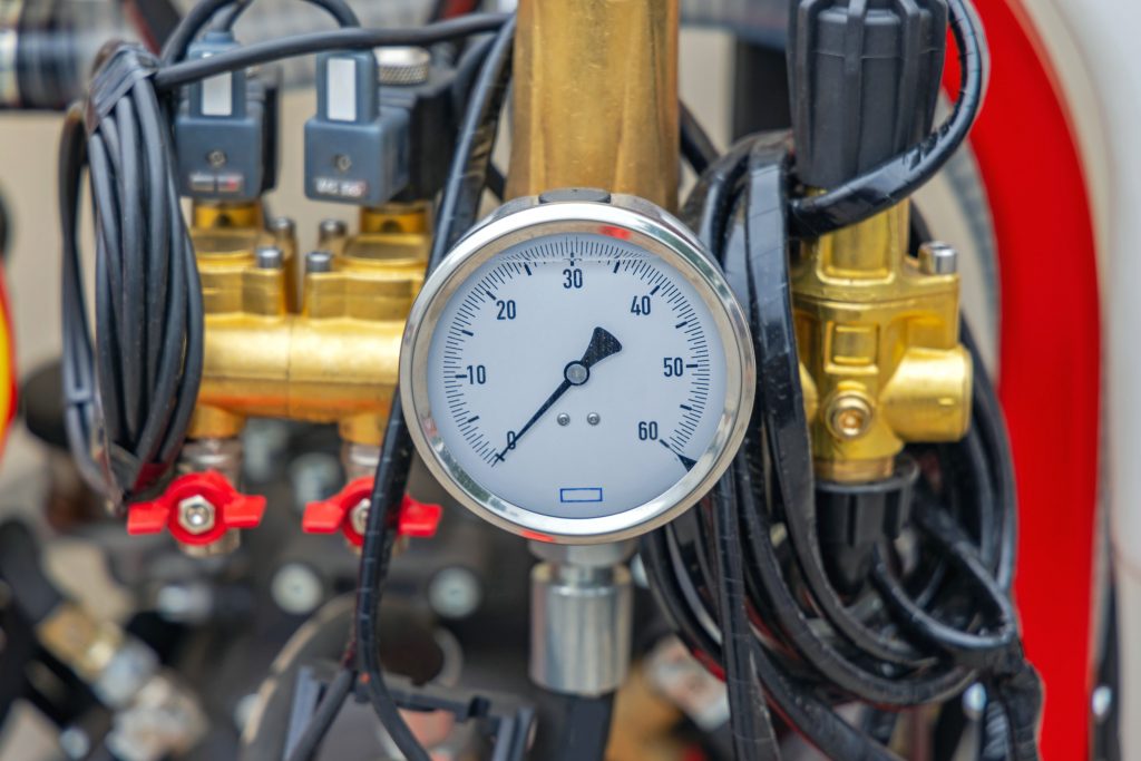
Pressure Gauges and Transmitters
Pressure gauges give operators real-time visibility of circuit pressures, while pressure transmitters feed data to control systems and logging equipment. These instruments allow operators to monitor pressure spikes, detect abnormal conditions, and verify that the system is operating within safe limits.
Pressure Switches
Pressure switches trigger automatic shutdowns or alarms when pressure exceeds or drops below preset thresholds. Applications include low-clamp pressure alarms on workholding systems and high-pressure shutdowns on test rigs. These devices add a layer of automated protection that does not rely on operator vigilance.
Burst Discs / Rupture Discs
In specialist applications requiring rapid, sacrificial overpressure protection, burst discs rupture at a defined pressure to relieve the system instantly. They must be replaced after any activation and are typically used where the speed of pressure relief is critical.
Load-Holding and Load-Sensing Systems
Load-holding valves lock actuators in position, while load-sensing systems adjust pump output to match demand, keeping pressures within safe limits while providing the force needed for the task.
All hydraulic pressure safety devices must be correctly specified for pressure range, fluid type, temperature, and environmental conditions to function reliably.
Pre-operation instrument checks:
- Pressure gauges are visible and reading within the expected range
- Pressure switches tested for alarm function
- Accumulator pressure indicators verified
- Filter clog indicators checked
- Temperature gauges or sensors are operating correctly
Hydraulic System Safety Standards and Regulatory Requirements
Hydraulic system safety standards exist to reduce accidents and ensure consistent minimum safety levels at design, installation, and maintenance stages. Compliance is not just a legal obligation—it reflects best practice developed over decades of industry experience.
Key European and UK frameworks relevant in 2024–2026 include:
- ISO 4413 – Establishes general safety requirements and guidelines for hydraulic fluid power systems and their components
- EN/ISO machinery safety standards – Requirements for hydraulic systems in machinery
- Pressure Equipment Safety Regulations – Requirements for pressure-containing components
- PUWER (Provision and Use of Work Equipment Regulations) – UK requirements for equipment safety and maintenance
- Machinery Regulation/Directive – Overarching framework for machinery safety in the EU/UK
These hydraulic system safety standards typically cover maximum allowable working pressure, safety factors for hoses and fittings, requirements for pressure relief paths, and guarding of moving parts. Critically, compliance is not just for original equipment manufacturers (OEMs). Owners and operators must maintain systems to these standards throughout the equipment’s life, including when replacing hoses or retrofitting components.
Risk assessments should specifically address hydraulic pressure hazards, considering worst-case scenarios such as line burst, loss of load, and uncontrolled motion. Safety devices must be shown to mitigate these risks effectively. The Health and Safety Executive in the UK provides guidance on managing pressure system risks, reinforcing the importance of proper design, maintenance, and operator training.
Practical compliance actions:
- Document relief valve settings and test dates for all circuits
- Maintain hose inspection schedules and replacement records
- Use only rated components matched to system pressure and fluid type
- Ensure operators are trained to recognise abnormal pressure behaviour
- Conduct periodic risk assessments that include hydraulic pressure scenarios
Best Practice Design Principles for Pressure-Safe Systems
Design-stage decisions have a lasting impact on pressure safety. Engineers and project managers responsible for new or upgraded hydraulic installations should prioritise the following:
Component Selection and Safety Factors
Select hydraulic components with appropriate pressure ratings and built-in safety factors. Hoses, fittings, cylinders, and valves should all be rated above the maximum working pressure, with margins to accommodate transient spikes and long-term fatigue.
Minimising Dead-Legs and Trapped Pressure
Design circuits to minimise dead-legs—sections of pipework where pressure can become trapped after shutdown. Where isolation is necessary, provide depressurisation points so technicians can safely release stored energy before maintenance.
Clear Relief Paths
Every pressurised section should have a defined relief path. Relief valves must be sized to handle the full flow capacity of the pump to prevent overpressure under any operating condition.
Separation of Pressure Zones
Where possible, separate high-pressure and low-pressure circuits using pressure-reducing valves and dedicated manifolds. This protects delicate components and simplifies fault diagnosis.
Clear Labelling
Label manifolds, valves, and test points with the maximum working pressure of each connection. This information helps technicians avoid errors during maintenance and repair work.
Design for Maintainability
Provide safe test ports, isolation points, and adequate access space for checking or replacing hydraulic pressure safety devices. Systems that are difficult to maintain tend to be maintained less often—or not at all.
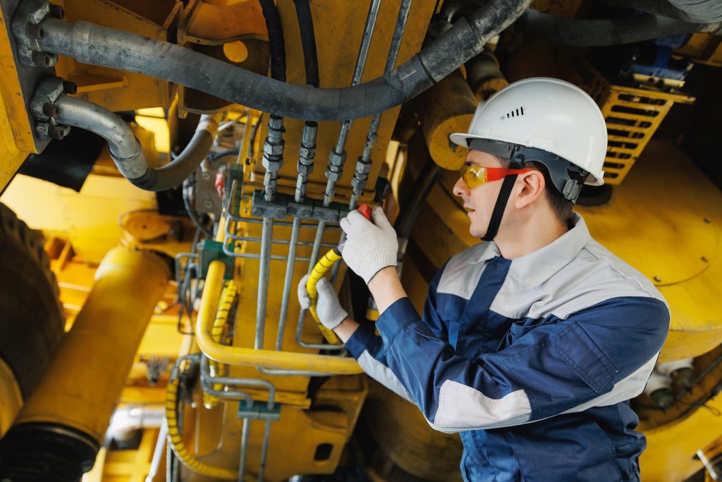
Operational Practices for Safe Hydraulic Pressure Management
Day-to-day operational practices determine whether well-designed safety systems actually protect people and equipment. Supervisors, operators, and maintenance engineers all play a role in maintaining safe hydraulic pressure management.
Safe Start-Up and Shut-Down
Before starting any hydraulic system, operators should verify that all guards are in place, safety devices are functional, and no personnel are in hazardous zones. On shutdown, follow procedures to bleed trapped pressure using designated depressurisation points. Never loosen fittings on pressurised lines—even at relatively low pressures, the sudden release of fluid can cause severe injuries.
Lockout/Tagout (LOTO) and Load Support
Before any work on cylinders, hoses, or valves, isolate the hydraulic system using lockout/tagout procedures. For raised loads, use mechanical supports such as props or stands—never rely solely on hydraulic pressure to hold a load in place during maintenance.
Personal Protective Equipment (PPE)
Appropriate PPE for hydraulic work includes:
- Face and eye protection rated for fluid splash
- Gloves suitable for contact with hydraulic fluid
- Flame-resistant clothing where ignition risk is present
- Steel-capped boots for work around heavy components
Diagnosing Leaks Safely
Never check for leaks with bare hands. Even at modest pressures, hydraulic fluid can penetrate skin through pinhole leaks. Use cardboard, wood, or dedicated leak-detection tools to locate leaks without direct contact. Fluid injection injuries require immediate surgical treatment—delaying can lead to amputation or worse.
Operator Training
Training should go beyond basic control use to include:
- Reading and interpreting pressure gauges
- Recognising abnormal pressure behaviour
- Responding to alarm conditions
- Understanding the function and location of safety devices
Operators who understand how their system works are far better equipped to recognise early warning signs and prevent incidents.
Quick reference: Safe operational practices
- Bleed pressure before loosening fittings
- Use LOTO and mechanical supports for all maintenance
- Wear appropriate PPE for hydraulic work
- Never check leaks with bare hands
- Report abnormal gauge readings or system behaviour immediately
Monitoring Pressure, Temperature, and Fluid Condition
Pressure safety is tightly linked to temperature and contamination. High temperature can degrade hydraulic fluid viscosity, reduce seal life, and change component behaviour in ways that raise the risk of overpressure events. Contamination—whether particulate, water, or air—can cause internal leakage, erratic valve operation, and accelerated wear.
Typical Monitoring Routines
| Check | Frequency | What to Look For |
|---|---|---|
| Pressure gauge readings | Daily/each shift | Values within expected range, no sudden spikes |
| Operating temperature | Daily | Stable temperature, no upward trend |
| Filter clog indicators | Weekly | Indicator not in bypass/warning zone |
| Fluid level and appearance | Weekly | Correct level, clear fluid without cloudiness or foam |
| Fluid sample analysis | Monthly/quarterly | Contamination levels are within acceptable limits |
Early Warning Signs
- Pressure spikes when actuators stall or reach the end of the stroke
- Slower movements at normal pressure indicate internal leakage
- Rising operating temperatures without increased load
- Noisy pumps (cavitation, air ingress, or wear)
Scheduled condition checks, combined with data from sensors on modern machines, help build a trend picture. Reacting to trends is far more effective—and safer—than waiting for a failure to occur.
Maintenance, Inspection, and Service for Pressure Safety
Even the best-designed hydraulic pressure safety systems degrade over time. Wear, vibration, contamination, and thermal cycling all take their toll on hoses, seals, and valves. Systematic maintenance is essential to ensure these components continue to protect the system and the people who work with it.
Scheduled Inspection
Inspection should cover all pressure-bearing components, with particular focus on those exposed to the highest pressures or duty cycles:
- Hoses: Check for abrasion, kinking, bulging, cracking, and incorrect routing
- Fittings: Look for leaks, corrosion, and loosening
- Cylinders: Inspect for rod wear, seal leakage, and mounting integrity
- Valves: Verify operation, check for external leaks, and confirm settings
Functional Testing of Safety Devices
Relief valves, pressure switches, and other hydraulic pressure safety devices require functional testing at defined intervals—typically annually or per OEM recommendation. Testing should verify that:
- Relief valves open at the correct pressure
- Pressure switches trigger alarms or shutdowns at set thresholds
- Accumulators hold the correct pre-charge pressure
Avoiding DIY Repairs
DIY repairs—especially hose “re-ending” with unapproved fittings—are incompatible with maintaining safe pressure capability. Such repairs often breach hydraulic system safety standards and may void insurance cover. Components that fail under pressure can cause catastrophic failures and serious injury.
Working with Specialists
Partnering with specialist hydraulic service providers ensures that pressure testing, fault-finding, and component replacement are carried out in line with best practice. Professional hydraulic service and maintenance deliver documented results, traceable components, and confidence that systems remain in good condition.
Top 5 maintenance tasks for pressure safety:
- Test and verify relief valve settings at scheduled intervals
- Replace hoses based on age, condition, or OEM recommendations
- Check and record the accumulator pre-charge pressures
- Inspect and test pressure switches and gauges for accuracy
- Document all maintenance and keep records accessible for audits
Creating a Hydraulic Pressure Safety Inspection Checklist
A site-specific checklist ensures nothing is missed and provides a clear record for compliance and audit purposes. A practical checklist should include:
- Visual inspection of all pressure-bearing components (hoses, fittings, cylinders, valves)
- Confirmation of relief valve settings against documented values
- Verification of pressure gauge accuracy (compare to calibrated reference)
- Checks for hose abrasion, kinking, and incorrect routing
- Accumulator pre-charge verification
- Pressure switch function test
- Documentation of test dates and next due dates for all critical safety components
Integrate this checklist into the organisation’s broader safety management system. Require sign-off by responsible persons and establish clear escalation routes if defects are found. Supervisors can implement this tool quickly on real equipment, making it a repeatable part of routine operations.
Human Factors, Training, and Culture Around Hydraulic Pressure Safety
Many hydraulic accidents—especially those involving pressure—stem from human factors. Rushing to meet deadlines, bypassing safety devices to “get the job done,” or simply misunderstanding how the system works can all lead to incidents that proper equipment alone cannot prevent.
Structured Training
Effective training goes beyond basic control use. Operators and technicians should understand:
- Hydraulic fundamentals: how pressure, flow, and force relate
- How to read and interpret circuit diagrams
- Pressure ratings of components and safe limits of the system
- How to recognise when a system is operating outside normal parameters
- The function and location of all safety devices
Safety Culture
A strong safety culture empowers operators to stop work if they suspect a pressure-related hazard—such as a damaged hose, an abnormal gauge reading, or a missing guard. Incident reports, near-miss logs, and periodic safety briefings raise awareness and share lessons learned across the team.
Visual Aids and Signage
Clear signage, colour-coding of pressure zones, and simple on-machine instructions help reduce errors, particularly for new or less-experienced staff. These aids make the right action the obvious action.
Common Mistakes to Avoid with Hydraulic Pressure Systems
The following mistakes represent high-impact errors that should be avoided at all costs:
Adjusting Relief Valve Settings Without Engineering Justification
Relief valves are set during commissioning for good reasons. Increasing the setting to “get more power” can exceed component ratings and lead to seal failure, hose rupture, or worse. Any adjustment should be documented and approved by a qualified engineer.
Using Incorrect or Unrated Replacement Hoses
Replacing a failed hose with whatever is available—rather than a properly rated equivalent—puts the entire system at risk. Hoses must match the pressure, temperature, and fluid compatibility requirements of the application.
Operating Equipment with Known Leaks
“It’s only a small leak” is a dangerous mindset. Even minor leaks can indicate failing seals or hoses, and fluid escaping under pressure can cause injection injuries or create slip hazards from oil spills.
Bypassing Safety Devices During Testing or Commissioning
Plugs, caps, and temporary connections must be rated for full working pressure. Bypassing relief valves or pressure switches “just for testing” removes critical protection at exactly the moment risk is highest.
Checking for Leaks with Bare Hands
This remains one of the most common—and most dangerous—diagnostic errors. Fluid injection injuries are easy to cause and difficult to treat. Always use cardboard, wood, or leak-detection tools.
Working Under Unsupported Loads
Hydraulic pressure can fail without warning. Never work under a load supported only by hydraulic cylinders—always use mechanical props or stands.
Each of these mistakes can escalate rapidly into a serious incident. Correct practice, reinforced through training and supervision, is the best protection.
Conclusion: Building Robust Hydraulic Pressure Safety into Every System
Safe hydraulic pressure management relies on three pillars: correctly specified hydraulic pressure safety devices, adherence to hydraulic system safety standards, and disciplined operation and maintenance. None of these elements works in isolation—all three must be in place for a system to operate reliably and safely over its full service life.
Overpressure protection in hydraulic systems is not optional. It is the foundation of preventing damage, avoiding catastrophic failures, and protecting people from serious injury. Every relief valve, every pressure switch, and every maintenance check contributes to this essential protection.
Take the time to review your existing hydraulic equipment for gaps in pressure protection. Are relief valves tested and documented? Are hoses inspected and replaced on schedule? Are operators trained to recognise abnormal conditions and respond appropriately? Addressing these questions now can prevent costly and dangerous failures later.
Organisations that work with experienced hydraulic specialists benefit from expert audits, optimised pressure settings, and maintenance routines that keep systems in good condition. Whether you’re commissioning new equipment or improving existing installations, professional support helps ensure that hydraulic pressure safety is built in—not bolted on as an afterthought.
Take action today. Protect your people, your equipment, and your operations by making hydraulic pressure safety a priority.